


Structure of a Closed-Circuit Evaporative Cooler
Jun 16, 2025
Leave a message
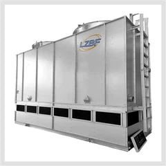
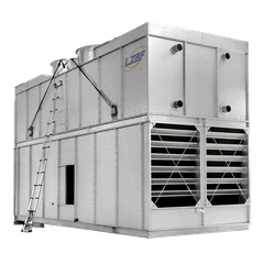
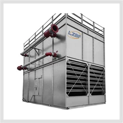
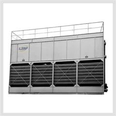
An evaporative cooler, also known as an evaporative cooling tower, primarily consists of a tower body, a high-temperature metal compensator, a water vapor injection device, an ash removal device, and an inlet flue gas distribution device.
Injection Device
In the evaporative cooler's duct adjacent to the end of the evaporative cooling flue, 8 to 12 high-pressure air mist spray guns are evenly distributed, depending on the converter capacity. To achieve evaporative cooling, the spray particles must be sufficiently fine (average 100 μm), necessitating a unique atomizing nozzle structure.
There are three atomization methods: nitrogen atomization, high-pressure atomization, and steam atomization. Nitrogen atomization and steam atomization are commonly used. The spray guns are a double-layer structure, with water flowing through the center pipe and air (steam) flowing through the outer layers.
A low water injection volume results in poor flue gas cooling and fire extinguishing effectiveness. A high water injection volume or water that fails to atomize can cause water to be carried with the dust, leading to scaling of the evaporative cooler's inner walls or settling, making it difficult to scrape away.
Therefore, the spray gun parameters are crucial. Domestic spray gun manufacturing has reached international standards.
Expansion Adjustment Device
To adjust for equipment displacement caused by thermal expansion and contraction of the evaporative cooling flue, an expansion adjustment device is installed at the junction with the evaporative cooling flue, acting as a "loop." There are two types of expansion adjustment devices: metal expansion joints and overflow water seals without contraction sections. Metal expansion joints are primarily used in evaporative coolers.
Tower Body
The tower body is constructed of welded steel plates and can be constructed in two or more sections for ease of transportation and hoisting. It features several entry holes or peepholes. The upper end is connected to the lower end of the expansion adjuster, and the lower end is connected to the U-shaped pipe of the ash discharger.
Ash Discharge Device
An ash discharge device is located at the lower part of the tower body. Dust separated by gravity is scraped by fan-shaped scrapers onto a chain ash conveyor, where it is then discharged through a pneumatic gate valve and a double-layer flap valve.
After each heat of steel is tapped, the ash must be carefully scraped, and the shape of the scraper chain must be constantly monitored for changes. Excessive ash accumulation in the banana bend of an evaporative cooler can create a "throat," increasing system resistance, leading to flames at the furnace mouth, increased load on auxiliary systems, and even equipment damage.
Flue gas distributor
Ash buildup on the inner walls of evaporative coolers is a common problem in dry dust removal systems. While there are many reasons for this buildup, such as poor atomization of the water spray from the nozzles, the root cause lies in uneven airflow distribution entering the evaporative cooler. As shown in the "Flue gas distributor" figure, the centerline of the water-vapor mixture sprayed by the spray gun is deflected toward the side walls of the vaporization flue under the influence of the airflow, forming vortices on both sides of the evaporative cooler. Areas where vortices form and areas splashed by the spray gun water are prone to scaling on the inner walls of the evaporative cooler.
Send Inquiry