
Working Process Of Counterflow Closed Circuit Cooling Tower
Sep 12, 2025
Leave a message
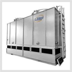
The counterflow closed circuit cooling tower is a highly efficient equipment in industrial cooling systems. The term "counterflow" derives from the opposite flow directions of air and spray water in the coil section. This equipment utilizes evaporative cooling principles to achieve efficient temperature reduction of process fluids in sealed pipelines, maintaining zero contamination and zero loss of the working medium throughout the process. Below is the detailed workflow:
1. High-Temperature Fluid Input
The high-temperature process fluid (such as water, oil, hydraulic oil, etc.) requiring cooling is delivered to the sealed coil inlet at the top of the cooling tower by a circulation pump after completing heat exchange in terminal equipment. The fluid circulates entirely within the completely sealed coil system, preventing any contact with the external environment.

2. Spray System Activation
Spray water from the sump is drawn through clog-resistant pumps, pressurized, and delivered to the spray system above the coil. Through precisely designed nozzle arrays, the spray water is evenly distributed into vertical downward curtains, completely covering the external surface of the coil to form a continuous water film.

3. Counterflow Air Organization
A high-power axial fan located at the top of the equipment generates strong suction, driving ambient air to flow upward from the air inlet at the bottom of the tower. When passing through the coil section, the air forms a complete counterflow pattern with the falling spray water.

4. Efficient Heat Exchange Process
This stage includes two heat transfer methods:
Sensible heat transfer: Heat from the high-temperature fluid inside the coil is conducted through the tube wall to the external water film
Latent heat exchange: The rising air stream directly contacts the falling water film, where partial water evaporation removes substantial vaporization latent heat
The counterflow design ensures maintaining the maximum temperature difference throughout the process, significantly improving heat transfer efficiency.

5. Cooled Fluid Output
The process fluid completes heat exchange and reaches the set temperature value, then returns to the working equipment from the coil outlet, forming a complete closed循环系统.

6. Moist Air Handling
The saturated moist air continues to rise under the fan's action, passes through high-efficiency drift eliminators to remove entrained water droplets, and is discharged from the tower. The drift eliminator can effectively control the drift rate below 0.001%.
7. Water Circulation System
Spray water falling back into the sump is filtered and重新参与循环. Through the coordinated operation of automatic makeup valves and blowdown valves, water quality stability and system water balance are maintained.

Technical Features:
Counterflow design improves heat transfer efficiency by 20-30%
Reduces footprint by 25-40% compared to crossflow designs
Enables three operating modes: dry, wet, and hybrid
Energy consumption reduces by 30-50% with variable frequency control
Suitable for applications requiring large cooling temperature differences
Send Inquiry